Engineered and functional silicone components
Parts where silicone performs a defined job — sealing, protection, tactile interface or movement — and the specification matters more than the appearance.
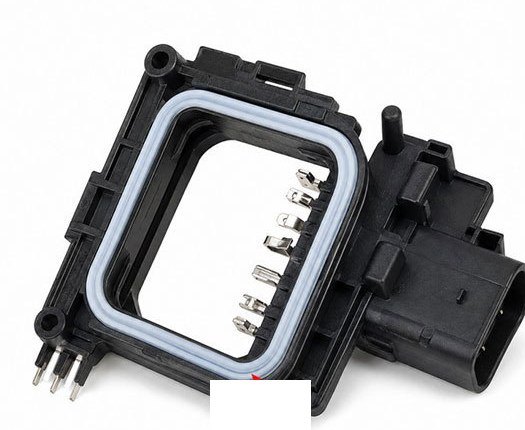
Function first: sealing, protection, interface
This is the deepest product direction and the one closest to the engineering capability behind the rest of the site.
Engineered functional silicone components
Components developed from a 2D drawing, 3D / CAD file, physical sample, existing component or a confirmed functional specification. Geometry, fit, material, function and manufacturability are reviewed before tooling.
Custom molded technical parts
Application-specific silicone parts developed around geometry, function, dimensions and technical requirements.
Seals & gaskets
Sealing components developed around fit, compression, contact surface and environmental requirements.
Protective boots & covers
Boots and covers for equipment, housings, connectors and exposed interfaces.
Interfaces & pads
Pads, interfaces and contact components for cushioning, sealing, protection or controlled contact.
Overmolded components
Silicone combined with plastic or metal inserts for integrated sealing, grip, protection or functional structures.
Repeat OEM components
Parts developed against approved specifications for repeat OEM production.
What we develop from
2D drawing
Sketches or drawings with key dimensions and sections.
3D / CAD file
CAD data for precise geometry and interface development.
Physical sample
An existing part used as the dimensional and functional reference.
Existing component
The component the silicone part must fit or protect.
Dimensions & tolerances
Key dimensions and allowable variation per requirement.
Material / hardness requirement
Grade and hardness targets reviewed for the application.
Functional requirement
Sealing, protection, cushioning or contact function defined per use.
Assembly interface
How the part fits with mating components and assemblies.
Material and process selection
Material and process selection depends on product function, geometry, environment, assembly conditions and project requirements.
Silicone grade
Grade selected for the application and environment.
Silicone hardness
Hardness selected for function, compression and feel.
Custom dimensions
Dimensions developed from drawings, CAD files or samples.
Wall thickness
Wall sections balanced for flexibility, strength and sealing.
Surface finish
Finish selected for friction, appearance and release.
Colour
Colour matched to confirmed references where required.
Insert / substrate integration
Plastic or metal inserts integrated into the part.
Overmolding structure
Overmolded structures reviewed at the design stage.
Design review before tooling
Technical requirements should be reviewed before tooling to reduce fit, sealing and repeat-production issues.
Dimensions & tolerance
Key dimensions and agreed tolerances confirmed before tooling.
Compression / sealing interface
Compression and contact geometry reviewed for the sealing function.
Hardness & elasticity
Hardness and elasticity balanced for function and fit.
Wall sections
Wall sections planned for filling, strength and flexibility.
Parting line & flash
Parting line placement and flash control reviewed per surface.
Material compatibility
Silicone reviewed against contact materials and the service environment.
Assembly fit
Fit with mating parts confirmed before production.
Sealing use cases and considerations
Custom sealing parts for enclosures and assemblies — gasket features, seal rings and waterproof structures, developed around groove fit, compression and the closing method.
Custom outlines & cut-outs
Gaskets molded to your drawing or sample, including custom outlines and cut-outs.
Thickness variation
Local thickness and step changes reviewed at DFM.
Seal rings & bead features
Molded bead and ring geometry developed for the sealing function.
Waterproof structures
Sealing designed around groove fit, compression and the closing method, then verified on samples.
Hardness & compression set
Hardness and compression behaviour selected for the seal and confirmed on samples.
Tolerance & tooling
Sealing features and tolerances are set at the DFM review so tooling matches the enclosure.
Compliance by application
Material documentation such as FDA- or LFGB-type testing support is reviewed for the specific grade where applicable.
Protection, fit and grip
Custom protective boots and covers for devices, controls and equipment — molded to your device dimensions with cut-outs for connectors, buttons and displays.
Device geometry & cut-outs
Boots and covers molded to your device dimensions, including cut-outs for connectors, buttons and displays.
Sealing & ingress review
Perimeter and compression designed around the closing method; enclosure-level ratings are validated on the complete assembly.
Grip & surface
Surface texture and hardness selected for grip, feel and handling conditions.
Material selection
Grade chosen for temperature exposure, cleaning agents and the service environment.
Wall thickness & flexibility
Wall sections balanced so the cover flexes where needed without losing protection.
Manufacturing review
Centre support, demolding and trimming reviewed at DFM.
Tactile structures and control interfaces
Custom silicone keypads and waterproof control interfaces for electronic devices — key web geometry, sealing, legends and housing fit reviewed together.
Molded buttons & key webs
Key web geometry tuned for a defined tactile response and repeatable actuation.
Waterproof control interfaces
Perimeter and compression design seals the interface against the housing.
Custom legends
Molded or printed markings, reviewed for legibility after molding.
Hardness & tactile feel
Hardness and web sections selected to match the required feel, then confirmed on samples.
Housing fit
Keypad fit and retention reviewed against your enclosure.
Insert & plastic integration
Where the design requires it, silicone combines with plastic or metal structures.
Carry and attachment components
Straps, sleeves, holders and attachment systems developed around connection geometry, wear and flexibility, and combined with metal hardware, plastic or textile where needed.
Straps & attachment systems
Strap and attachment components with integrated hardware for lifestyle and outdoor products.
Sleeves & holders
Sleeves and holders shaped around the product interface and retention.
Connection geometry
Loop, pin and anchor geometry reviewed for pull-off and retention at DFM.
Wear & flexibility
Flexibility and reinforcement balanced for repeated use at the attachment points.
Silicone + textile / plastic / metal
Silicone combined with straps, textile, plastic or metal hardware where the product requires it.
Outdoor durability
Material selected for UV and temperature resistance where the product is used outdoors.
Colour matching
Colours matched to brand references and confirmed through sampling.
Process routes
Custom silicone molding
Compression and transfer molding to your drawings.
LSR injection molding
Liquid silicone for detailed geometry and repeat consistency.
Silicone overmolding
Silicone bonded onto plastic, metal or inserts.
Silicone + plastic structures
Rigid plastic with flexible silicone areas.
Multi-material development
Silicone combined with other materials as one product.
Accessory components
Straps, sleeves, grips and holders around existing products.
Where functional components are used
Electronics & wearables
Device covers, keypads, interfaces, seals and overmolded structures.
Beauty & personal care
Contact surfaces and device components for personal-care products.
Fitness & wellness
Grip, protection and wearable components.
Outdoor & travel
Protective and carry-related functional parts.
Pet products
Functional molded parts for pet product programmes.
Frequently asked questions
Can you match device geometry for boots and covers?
Yes. Boots and covers are custom molded to your device dimensions, including cut-outs for connectors, buttons and displays. Beyond fit, protection has to respect the device itself: wall and cut-out choices affect heat dissipation, charging-port access and button actuation, so these are reviewed with the device or full geometry on hand before the design is frozen.
How should I choose keypad contacts such as carbon pills, conductive ink or metal domes?
The contact type sets the operating feel, the electrical life and the cost of the assembly. Carbon pills on silicone webs are the robust default for silicone rubber keypads: low cost, good wear behaviour and stable contact resistance over many presses. Conductive ink — printed silver or carbon — keeps the contact layer very thin for compact layouts, but wears earlier under heavy use. Metal domes deliver the crispest tactile snap and precise actuation forces, but they are separate components assembled onto a PCB or dome sheet rather than part of the moulded keypad. Choose by actuation feel, required press life, assembly architecture and budget. Share the assembly structure, contact conditions and functional targets, and we will propose the keypad and contact combination with samples to verify feel and life.
How can backlit silicone keypads control light leakage and legend wear?
Backlit keypads are a joint appearance-and-function problem, so light behaviour and legend durability have to be engineered together. Light control comes from the silicone formulation and wall thickness — translucent base layers with selectively opaque areas limit where light escapes — while legends sit either under the surface, moulded or printed on the underside so wear never touches the symbols, or on the surface where appearance is sharper but protection is needed. The trade-offs to settle: which keys must light, how even the illumination must look, ambient conditions, and how many actuation cycles the legends must survive. These are verified on samples under lit and unlit conditions, not on drawings. Share the keypad layout, lighting intent and usage profile, and we will propose the structure and legend approach with lit samples for joint approval.
How should plug insertion life and tether retention be validated?
Waterproof plugs and their tethers fail through wear, not through material breakdown — so validation has to reproduce the motions that cause wear. For insertion life, define the cycle the plug will really see: insertion and removal force, angle, frequency and whether it is seated by hand or tool, then run the cycles and confirm the seal still meets its rating afterwards. For tether retention, test pull force and direction on the anchored end after the plug has been flexed and pulled the way users actually handle it. Set acceptance numbers before sampling — a vague “should stay attached” cannot be inspected. Share the assembly structure, the host port and the usage pattern, and we will propose the plug-and-tether design with the wear and retention checks built into sample approval.
What information is needed for quotation?
Drawings, CAD files or samples, application and fit requirements, material and hardness targets, quantities and packaging expectations.
Where to go next
Developing a functional silicone component?
Send the drawing, the function it must perform and the environment it works in. We review the specification and process route, then reply with the next steps.