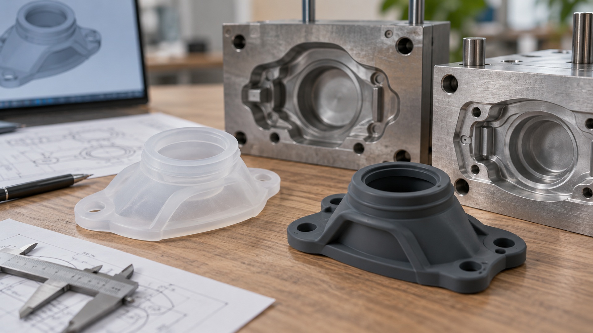
How should wall thickness and local reinforcement be designed for silicone parts?
Silicone parts often look geometrically simple — a grip, a seal, a sleeve — and that simplicity is deceptive. Small choices about wall thickness, corners, and ribs decide whether the part fills cleanly, demolds without tear, and survives being flexed a few thousand times. A design that works as a hand prototype may still be difficult to mold consistently at production scale.
The goal is to control both molding risk and in-service breakage. That means keeping sections uniform, taking the stress out of corners, and putting material only where the part actually needs it.
Keep wall sections as uniform as possible
Sudden changes in thickness cause trouble in silicone just as they do in plastics, but for slightly different reasons. Thick sections cure slowly from the outside in, so an over-thick area can under-cure in the middle while the surface looks done. Thin sections beside thick ones fill and cool unevenly, inviting warpage, short shots, or dimensional drift.
Design toward a consistent wall. Where a part must be thicker for strength, transition gradually rather than stepping abruptly, and let the mold designer advise where the cure time is actually being set.
Radii, not sharp corners
Sharp internal corners are where silicone parts tear. Under flex or assembly, a sharp radii-free corner becomes a stress concentration that starts a crack and walks it across the part. Soften inside corners with a radius, especially at the root of a boss, a rib, or a living feature that bends.
This is also a demolding concern. A flexible silicone part can flex out of modest undercuts far more forgivingly than rigid plastic, but sharp internal corners still hang up during ejection and can tear on the way out.
Reinforce locally, not globally
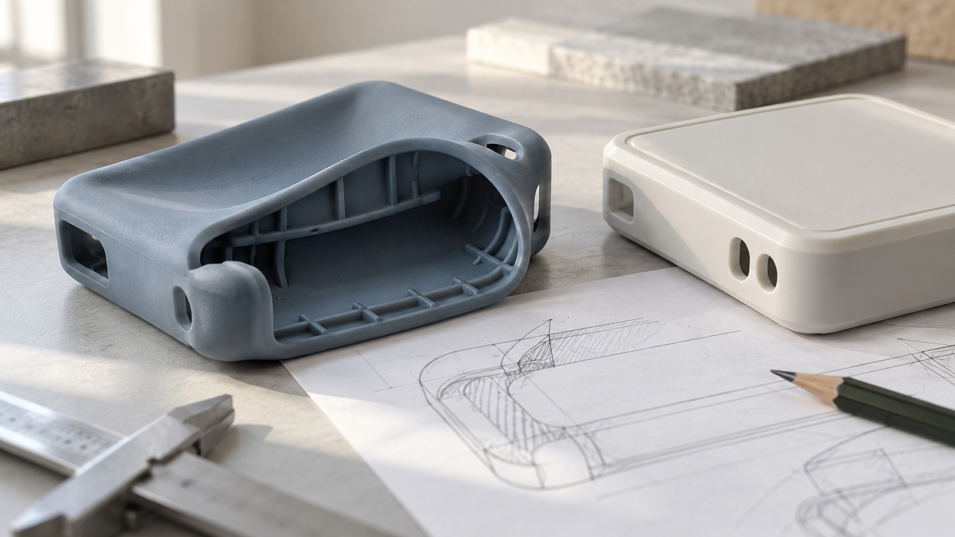
You usually do not need a uniformly thicker part. You need extra material in the spots that actually take the load or the tear:
- Around holes and openings. Holes are common tear points; a slight boss or thicker rim distributes the stress.
- At roots and junctions. Where a rib or arm meets the main wall, blend the transition rather than leaving a sharp notch.
- At clip and snap features. The flexing root is where the part will fatigue; reinforce and radius it there.
- Thin membranes. Very thin walls are prone to pinholes and tears; if a membrane must be thin, frame it with a thicker border.
Adding material only where it is needed keeps the part soft and light where it should be, without over-building the whole thing.
Ribs and bosses deserve the same restraint. A rib that is too thick relative to the wall sinks or cures unevenly; keep ribs modest in section and blend them into the wall rather than butting them squarely. Thin membranes, on the other hand, are vulnerable to both pinholes and tears, so frame any very thin flexible area with a thicker border that carries the stress. The goal is a section that cures evenly and flexes where you want it to.
Demolding and the mold come into it
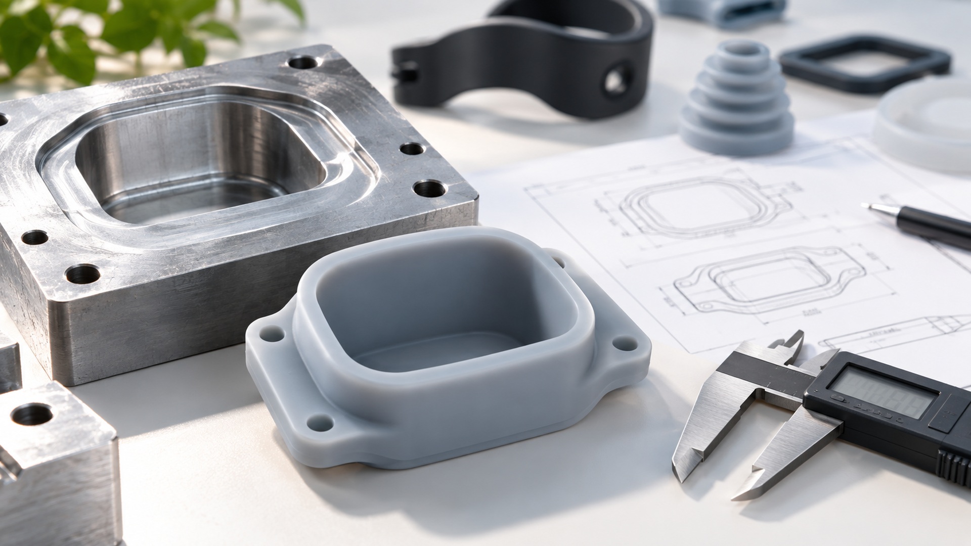
Wall design cannot be separated from how the part leaves the mold. Undercuts, ribs, holes, thin membranes, and the demolding direction all affect whether the part ejects cleanly. Before steel is cut, review CAD and 2D drawings together and mark:
- Critical dimensions and appearance zones.
- Sealing or retention interfaces where small shifts change function.
- Features where a dimensional change could break the fit with mating plastic, metal, or textile.
The point of DFM is not to flatten every interesting detail; it is to find where manufacturing variation actually matters.
Turn vague language into an acceptance standard
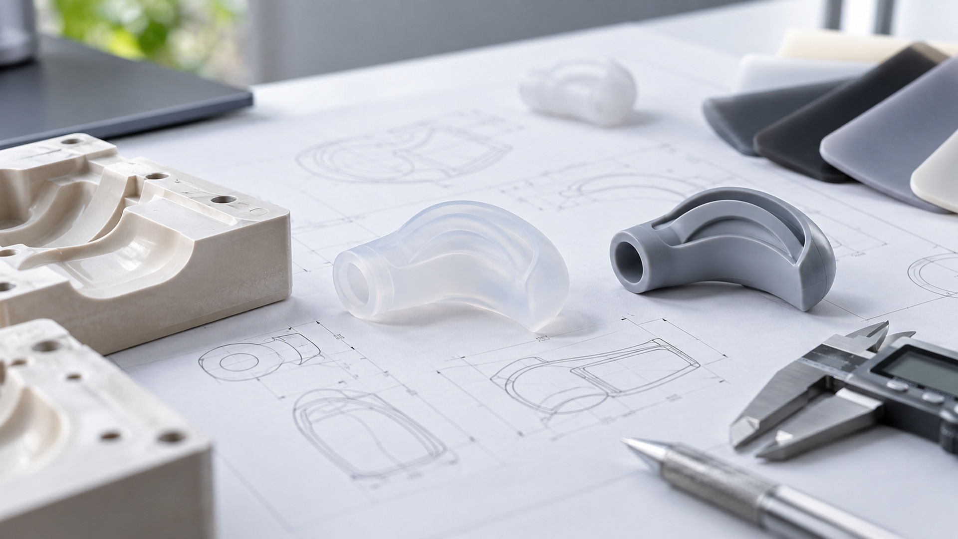
"Durable" or "tough" cannot be molded. Convert intent into something the design and QC can act on:
- A controlled reference — approved sample, wall-callout drawing, and signed visual standard.
- Critical characteristics — the wall thickness at load points, radii at stress roots, and flexed features.
- A test condition — how the part is flexed, stretched, or assembled.
- An acceptance rule — which cracks, tears, or dimensional drift fail the part.
- A revision record — the wall design and sample version approved.
Prototype success proves the form; only molded parts prove the design survives production variation and flexing.
Questions to ask the supplier
- Where in my design do you see fill, vent, or demolding risk?
- Are any wall sections so thick they risk under-cure?
- Where should I add radii or local reinforcement to prevent tearing?
- Which undercuts can the flex handle, and which need side actions?
- How will critical wall and radius dimensions be checked?
- What changes after T1 would require re-validation?
Credible answers point to specific stress points in your geometry. "It will be fine" is not a DFM review.
Conclusion
Designing silicone walls is about distributing material sensibly: uniform sections to fill and cure evenly, radii instead of sharp corners to stop tears at the root, and local reinforcement around holes, clips, and flexing junctions rather than making the whole part thicker. Run that through DFM before steel is cut, mark where variation matters, and the part molds cleanly and flexes instead of fails.