How do silicone shrinkage and flexibility affect achievable tolerances?
Drawing a silicone part to the same tolerances you would use on an injection-molded plastic is a reliable way to set up a failure. Silicone behaves differently twice over: it shrinks as it cures and cools, and it flexes under your calipers. Both effects widen the tolerance you can actually achieve, and a tolerance that ignores them is one the factory cannot hold — or measure.
The practical task is to agree on critical-to-quality dimensions that are both manufacturable and measurable. That means understanding where shrinkage comes from, accepting that soft parts deflect, and reserving tight tolerances for the features that truly need them.
The mold is cut larger than the part
When silicone cures and cools, it shrinks. The mold cavity is therefore machined slightly larger than the finished drawing, scaled by a shrink factor. Get that factor wrong and every dimension on the part lands off target — not because the factory is sloppy, but because the steel was sized for the wrong shrink.
Shrinkage is not a single number. It varies with the durometer, the wall section, and the process — LSR and HCR do not shrink identically. This is why a supplier that knows the grade and geometry can predict it, while a generic shrink assumption produces parts that never quite fit.
A soft part moves under the calipers
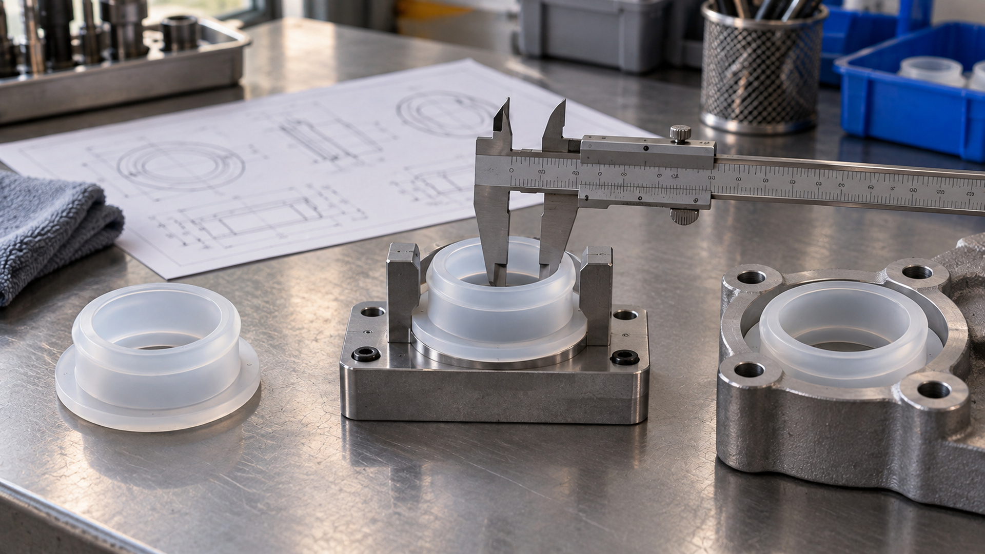
The second problem is measurement itself. Press a caliper onto a flexible silicone feature and the part deflects before the reading settles. Two inspectors measuring the same dimension can get two different numbers simply by how hard they squeeze.
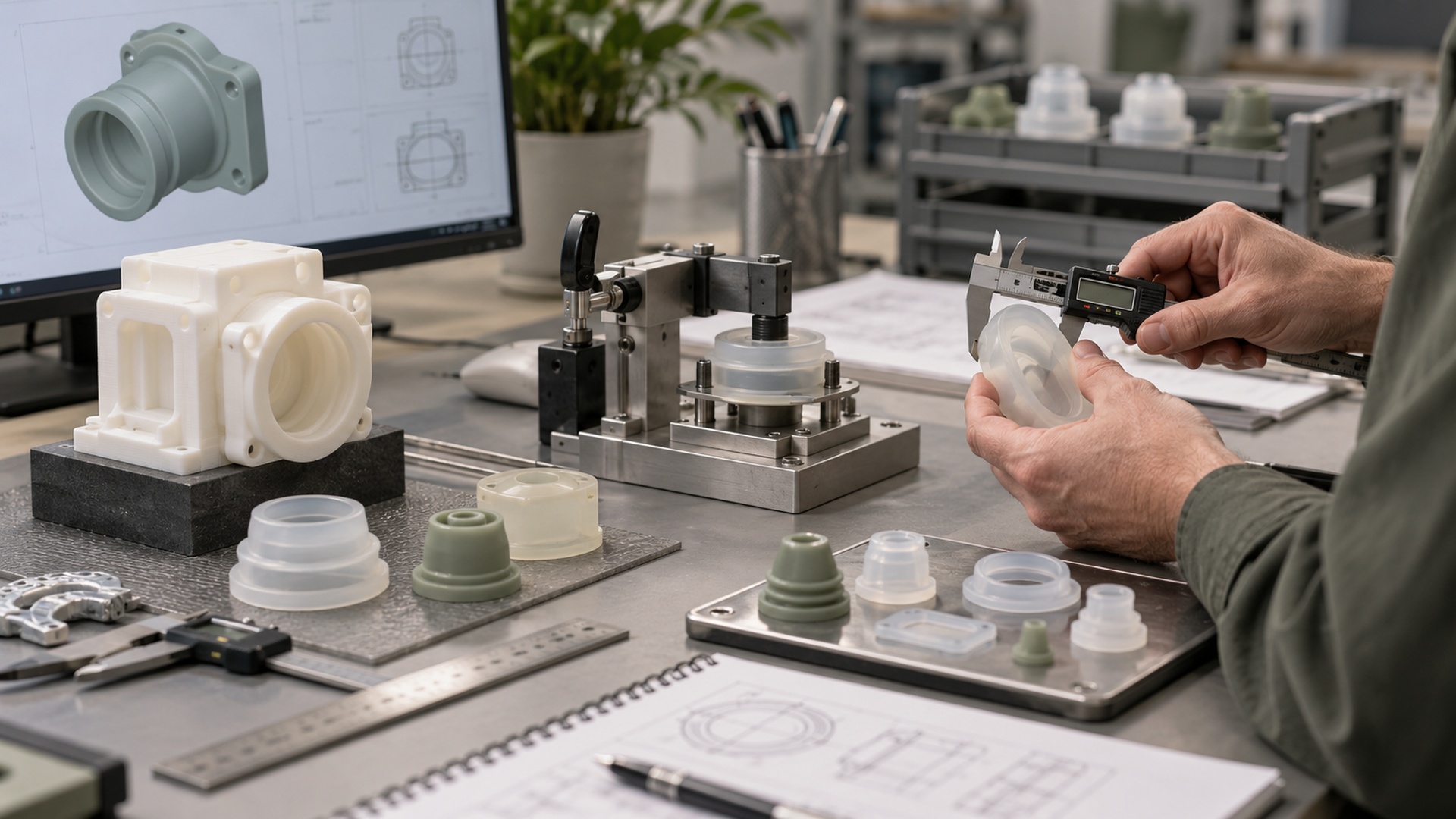
This means a tight tolerance on a free-flexing feature is not just hard to hold — it is hard to read consistently. Where a dimension really matters, measure it in a controlled fixture or in its assembled state rather than freehand. Where it does not, stop drawing it to a tolerance the gauge cannot resolve.
Reserve tight tolerances for what matters
Not every dimension needs to be tight. Silicone's flexibility is actually forgiving on cosmetic and non-critical surfaces — it will flex into place. Spend the tolerance budget where it pays off:
- Functional interfaces. Seal lands, mating fits, actuation travel — these earn tight tolerances.
- Cosmetic and free surfaces. Looser tolerances are acceptable and usually necessary.
- Assembled, not free-state, dimensions. Let the housing or mating part locate the flexible feature rather than over-controlling it.
Negotiating the CTQs up front — which dimensions are critical and which can follow a loose standard — is what keeps the drawing realistic instead of a wish list.
Design around flexibility rather than fighting it. Where two parts must locate, let the rigid plastic or metal feature carry the precision and let the silicone flex to it, instead of trying to hold a tight dimension on a soft feature. Small chamfers, generous clearance, and a flexible interference that assembles easily all absorb the variation silicone naturally produces — for free, without tightening the mold.
Tolerance stack-up with the mating parts
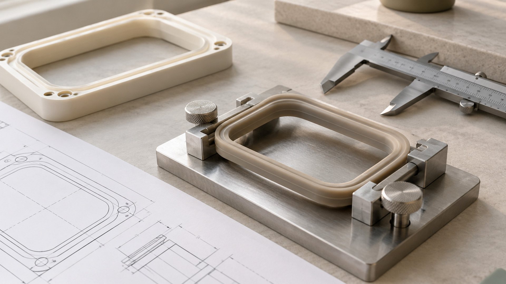
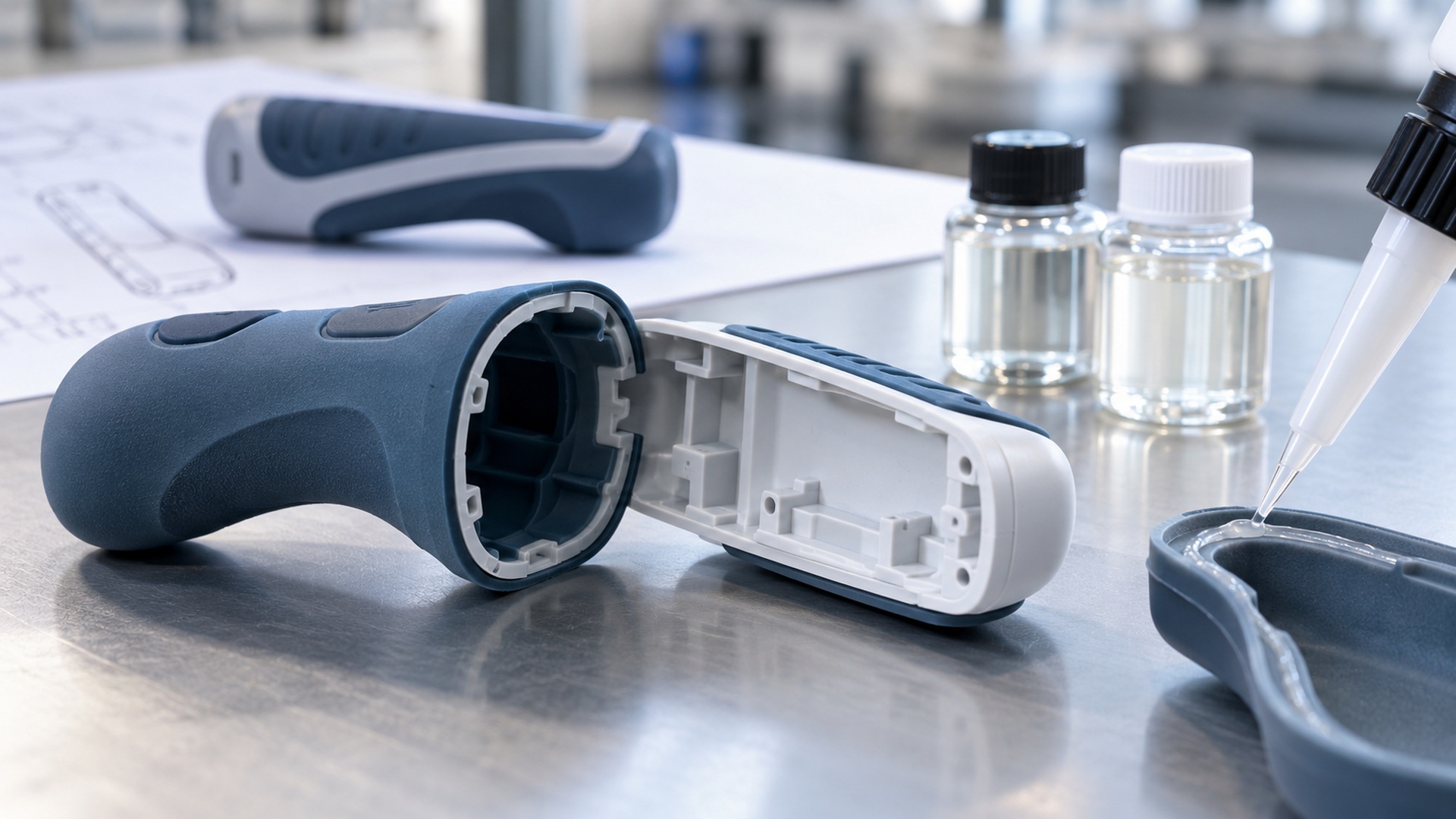
Silicone rarely lives alone. Its fit against plastic, metal, glass, or textile has to be reviewed as a stack-up. The flexible part can absorb some variation, but only if the design leaves it room. Before steel is cut, mark the critical interfaces where a small dimensional shift changes function, and the appearance zones where a visible seam or flash would be unacceptable.
The point of that review is not to make the part perfect on paper; it is to identify where manufacturing variation actually matters and where it is harmless.
Turn vague language into an acceptance standard
"Precise fit" or "tight tolerance" without a rationale cannot be inspected. Convert intent into something measurable and realistic:
- A controlled reference — approved sample and signed, dimensioned drawing.
- Critical characteristics — the specific dimensions that govern fit, seal, or actuation.
- A test condition — how and where the flexible part is measured (fixture, assembled state, free state).
- An acceptance rule — the tolerance on each critical dimension, and the looser standard elsewhere.
- A revision record — the shrink assumption and drawing version the tool was built from.
Prototype parts do not reveal production shrink variation; the T1 samples from the steel mold do, and those are when the shrink factor is confirmed.
Questions to ask the supplier
- What shrink factor did you use for this grade and wall section?
- Which dimensions are realistic to hold, given the flexibility?
- How do you measure flexible features consistently — in a fixture or assembled?
- Which critical interfaces did you flag in the stack-up review?
- How will T1 samples confirm or correct the shrink assumption?
- Which features are you suggesting we relax to a looser tolerance?
Credible answers name the shrink assumption and separate critical dimensions from cosmetic ones. "We'll hold tight tolerance everywhere" is not a manufacturable plan.
Conclusion
Silicone tolerances are set by two physical effects: the part shrinks as it cures, so the mold is oversized by a grade-specific shrink factor, and it flexes under measurement, so free-state dimensions cannot be read to plastic-style precision. The way out is to negotiate critical dimensions up front — tight on functional interfaces, loose on cosmetic surfaces, measured in fixtures where it counts. Draw to what the material actually does, and the part fits instead of arguing with the gauge.